How Can We Make an OTDR Perform Better in the Testing Task?
As the development of FTTx is very fast, especially FTTH (Fiber to the Home), that means Telecom providers/operators need serve very large quantity of subscribers. So telecom providers need build and maintain more and more fiber optic networks. Therefore, useful testing instruments for acceptance, troubleshoorting and maintaining fiber optics networks are very important and necessary. An OTDR is the right test instrument for telecom engineers in the field. Then, how can we make an OTDR perform better in the real testing tasks? Of course, the OTDR quality is very important. Besides that, some knowledge you must be known about OTDR is necessary too.
1. Principles of OTDR
An OTDR (Optical Time Domain Reflector) is a high precision optical testing instrument that use the theory of Rayleigh scattering and Fresnel reflection. It is widely used in the maintenance, construction and monitoring of an optical fiber line. All the important parameters like fiber length, optical loss, connection loss, broken or twisted point and etc. of a fiber can be shown on the OTDR. When the light transmits along a fiber, it would be scattered to various directions caused by the difference of properties of the transmission medium, this phenomenon called Rayleigh scattering. During the scattering process, some of the light will be scattered along the absolutely converse direction, this phenomenon is called Rayleigh back-scattering. It provides some details about the fiber length. The parameters about fiber length can be got by calculation with the parameter of time (This is the derivation of TD in OTDR——Time Domain).
These back-scattering signals shows the loss level of a fiber and through these information, OTDR can generates a backward oblique trace which reflects several important attributes of an optical fiber. When the light, transmitting downward along the fiber, meet a different density medium, a part of the light will be reflected, this phenomenon is called Fresnel reflection. There are many reasons can cause the changing of the medium density like a little slot at the splicing point, a broken of fiber or etc. This phenomenon is usually used to locate the discontinuous point. Compare to the Rayleigh scattering, the consuming amount of the light in Fresnel reflection is much more then it is in Rayleigh scattering. The power of Fresnel reflection is tens of thousands times to the back-scattering's. The reflection level depends on the changing grade of refraction ratio.
Formula of the distance: distance = (c/n)×(t/2) Here:
c is the light speed traveled in vacuum(2.998×10⁸m/s)
t is the delay between launching pulse and receiving pulse
n is the refraction ratio of the testing fiber(specified by manufacturer)
When display the whole trace, each point of the trace represents the average value of several sampling points. By zoom in and zoom out function, the value of each sampling point can be got.

2. OTDR's Events Type
The events on an OTDR's trace are all the points that the value of power loss fluctuates abnormally. It usually contains various types of connection and bending, crack, broken and etc. The event points marked on trace with special marks are the abnormal points in a fiber that cause the excursion of a normal trace.
The events can be divided into Reflection-event and Non-reflection-event
2.1 Start event
The Start-Event on an OTDR trace is the initial point. Under the default setup, Start-Event is located on the first event (usually it is an connection between the OTDR launching port and the connector of a fiber) of a fiber. It is a Reflection-event.
2.2 End event
The End-Event on an OTDR trace is the end point of a fiber. Under the default setup, End-Event is located on the last event(usually it is an end face or a broken down point of a fiber). Usually, it is a Reflection-event.
2.3 Reflection-event
The phenomenon on a trace that some power of the optical pulse is reflected called a reflection event. Reflection-event is displayed as a peak signal on a trace.
2.4 Non-reflection-event
The phenomenon on a trace that there exists some abnormal loss in a optical line, but no reflection occurred is called a Non-reflection-event. It is displayed as a drop with no peak on a trace.
2.5 Event detection
OTDR launches a bunch of optical pulse into a under-test fiber, receives the returned optical signal and starts calculating the distance from an event. The more the distance from the event is, the longer the returning time is cost. According to the receiving time, distance can be calculated. By detecting the trace generated by the returned optical signal, the attributes of the fiber itself, the connector of the fiber, adaptor in the fiber and splicing point in the fiber can be confirmed.
3. Analysis of OTDR's Trace
OTDR can auto analyze a tested trace, the position process shows below:
Get the reflection events generated by connectors or mechanical splicer.
Non-reflection events(usually it is splicing points or macro bending).
End: the first point which the loss of it is over the threshold would be scanned as the end of a trace.
Events list: event type, loss, reflection and distance.
3.1 Normal Trace


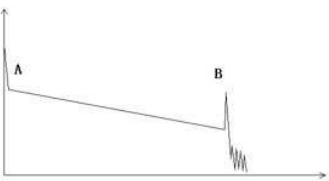
A normal trace shows as above, the A mark is a start-peak and the B mark is an end-reflection-peak. The tested trace is oblique, the total loss will become bigger with the increasing of the fiber length. The total loss(dB) divides total length is the average loss(dB/km) of a fiber.
3.2 Trace with Jumper Connected


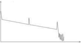
If there is additional reflection peak in a tested trace, this may be caused by a connection point or some other reasons. Anyway, appearance of the reflection peak shows that the two connecting surfaces of the connection are smooth. The smoother the connection surfaces are, the higher the reflection peak is.
For an instance, if a broken optical line is under test, the OTDR trace will show a broken point. After a maintenance of this line, use the OTDR test it again, we may see a reflection peak replacing the broken point on the OTDR trace, this shows the maintenance is done.
3.3 Trace with Broken Point


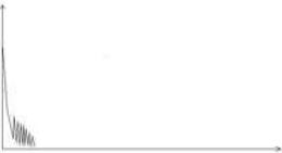
If the tested trace is just like the figure shows above, this might be caused by several reasons like:
a. a bad connection between the connector and the lunching port
b. the optical pulse cannot be launched into the optical fiber
c. a short distance broken point of the tested fiber from the initial connection
d. the preset testing distance and pulse width is larger.
To fix this problem, we should:
a. Check the connection of the connector and the launching point
b. Reset the test parameters, decrease the preset distance and the pulse width.
If the problem still exists, we could estimate:
The connector of the test fiber is broken or polluted.
a. The launching port on the OTDR is broken or polluted.
b. The distance of the broken point of the from the initial connection is too close.
3.4 Trace with Non-reflective Event


There is a common phenomenon that an obvious step is on the middle of a tested trace, it often caused by a fiber bending, fiber knot, being pressed by something heavy or a fuse splicing point. The step means a bigger loss of a fiber, it is also called event point. If the direction of it is downward, it could be called non-reflection event. If the direction is upward, we can call it reflection event.
Sometimes, the loss value could be a negative value, it does not means the loss does not exist. It is common phenomenon called miss matched fibers or gainer, it is by a connection of two fibers with different back scatter coefficient, the scatter coefficient of the back fiber is large than the front one's. In addition, the different refract ratio also can cause the phenomenon. To avoid it, we could test a fiber bi-directionally.
3.5 Abnormal Condition


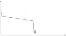
The situation that there is no reflection peak at the end of a trace shows above should be paid attention on. If the distance of the tested fiber is available and the distance shown on OTDR is not equal to the original distance, this shows that the fiber might be broken down or twisted and the bending radius of it is over limited. The distance shown on OTDR is the position of the fault point.
This phenomenon is often used in maintenance. If a fiber is uncertain, we can bend a fiber and make sure the bending radius is over limited, then use real time testing function of the OTDR to confirm the fiber.
3.6 Distance is Too long


This situation often happened in a long distance testing, caused by under-range dynamic range of the OTDR that the energy of it can not support a long distance transmission or caused by a under-range preset testing range of distance or pulse width corresponding to the actual fiber length.
To avoid this situation, adjust the testing distance and the pulse bigger and extend the sampling time.
4. OTDR Optimizing Tool - Fiber Optic Launch Leads to Eliminate OTDR's Dead Zone

4.1. Guide fiber
Use an guide fiber to figure out the character of connector. By adding this fiber we could move the fist connector out of the blind area.In the same way we could use this way to figure out the character of last connector.
2. About guide fiber
Proper length of Guide fiber is 100~1000m, it depends on the blind area of OTDR. In theory, minimum length of guide fiber should be two times longer than attenuation blind area , but it should be longer in practice.
5. How to use an OTDR?
How to use an OTDR? Every different brands have their own operation manual. Well, setting the proper parameters is one of the important steps. At the fist time using OTDR, if users choose some testing parameter which is not suitable to the real condition may cause the bad result. Users should take Testing range,pulse width and wavelength into consideration.
5.1 Setting proper testing range
Testing range means maximum display range.This parameter will indicate how long will OTDR display on its screen.this range must longer than testing fiber,Usually we choose range which is 20% longer than testing fiber.Take note that testing range should not has large difference with testing fiber,Otherwise it will affect the effective resolution and overlarge testing range will result in the generation of huge and useless data(see Figure 1).


Figure 1
5.2 Setting proper pulse width
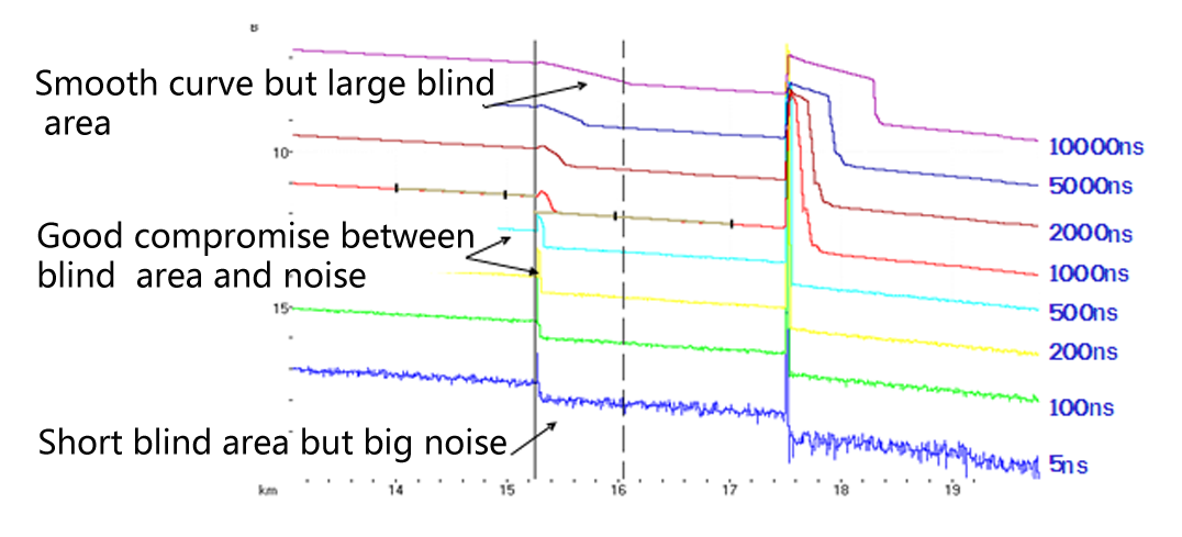
Pulse width and blind area, dynamic range are directly related to the maximum length ,in below picture, use ten different pulse width to test one testing fiber.the smallest pulse width result in the smallest blind area and the most terrible noise. The longest pulse width result in the smoothest curve and almost 1km blind area(see Figure 2).


Figure 2
It is obviously at the top of testing fiber influence on Pulse width , in below chart,we cant detect the first connecting point locate in the 540m by large pulse width.(see Figure 3)


Figure 3
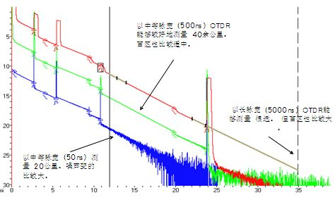
Dynamic range decided by Pulse width,larger pulse width will spend more optical power,but it reach further.(see Figure 4)


Figure 4
5.3 Setting proper wavelength
Proceed test with same fiber but different wavelength we will get different result. Longer the testing wavelength is,more sensitive of the bending, in below chart ,first splicing point has bending problem,splicing loss value under 1550nm is bigger than that under 1310nm. the other points are similar with 1310nm and 1550nm.This phenomenon indicate that this fiber is just bended at the first point. If it's possible please alway compare the point state under 1310nm and 1550nm and judge whether it's bended or squashed.(see Figure 5)


 Figure 5
 5.4 Set proper test time
In averaging mode, long testing time could reduce noise during the data sampling and Improve precision to get better and smoother curve(see Figure 6).


Figure 6
6. How to choose an OTDR?
There are a lot of OTDR models for different test and measurement needs in the market. How to choose the right one OTDR? A comprehensive understanding of OTDR knowledge and the application will help make the choice. Moreover, based on your specific need, you should answer the following questions before looking for an OTDR:
What kind of networks will you be testing?
What fiber type will you be testing? Multimode or single-mode?
What is the maximum distance you might have to test?
What kind of measurements will you perform? Construction, troubleshooting or in-service?
And when choosing an OTDR, you should take these factors into consideration:
Size and Weight: it is very important if you have to climb up a cell tower or work inside a building.
Display Size: 5" should be the minimum requirement for a display size; OTDRs with smaller displays cost less but make OTDR trace analysis more difficult.
Battery Life: an OTDR should be usable for a day in the field; 8 hours should be the minimum.
Trace or Results Storage: 128 MB should be the minimum internal memory with options for external storage such as external USB memory sticks
Bluetooth and/or WiFi Wireless Technology: wireless connectivity enables easily exporting test results to PCs/laptops/tablets
Modularity/Upgradability: a modular/upgradable platform will more easily match the evolution of your test needs; this may be costlier at the time of purchase but is less expensive in the long term
Post-Processing Software Availability: although it is possible to edit and document your fibers from the test instrument, it is much easier and more convenient to analyze and document test results using post-processing software
At 3S Telecom, the OTDRs offered range from basic, affordable models to high end, advanced models. If you have any specific needs, 3S Telecom also offers customized OTDRs with any specification you desire.


